- Review
- Open access
- Published:
Seismic analysis, design, and retrofit of built-environments: a procedural review of current practices and case studies
Journal of Infrastructure Preservation and Resilience volume 3, Article number: 11 (2022)
Abstract
This paper presents a synthesis of current practices in regard to the seismic analysis, design, and retrofit of built-environments. Background information on the behavior of existing buildings subjected to earthquake loadings is gathered and rehabilitation methodologies are elaborated. The first part of the review examines design standards and guidelines that are used in the structural engineering community. These documents are mandatory for the legal adoption of a model code by the governing jurisdiction where the building in question is to be located. The second part discusses retrofit procedures alongside specific provisions dominating the requirements and techniques appertaining to ground motions. The third part handles case studies emphasizing an upgrade of school buildings that are non-conforming to contemporary specifications and guidelines. For substantiating the performance of proposed methodologies, laboratory tests are conducted in conjunction with finite element analysis, which form the technical foundation of site implementations.
Introduction
The functionality of constructed facilities under seismic loading needs to be maintained within a tolerable range of damage or their constituents may fail in a ductile manner attempting to ensure user safety. Since the 1960s when extensive research commenced to embrace earthquake-related subjects, dramatic improvements have been made in terms of modeling and design approaches [1]. Unexpected catastrophic events often lead to upgrading established provisions. For example, the 2011 failure of the Fukushima nuclear power plant in Japan prompted the reevaluation of seismic risks in the United States [2]. Despite the remarkable advancement of analysis techniques and corresponding practice guidelines, concerns still remain about the operation of built-environments that were designed without considering the stringent requirements of contemporary structural codes and specifications. This is particularly crucial when it comes to seismically deficient buildings because the occurrence of collapse may be sudden and significant economic impacts ensue.
Structural retrofit has emerged as a promising solution in lieu of reconstruction and considerable endeavors have been expended around the world [3,4,5]. Accordingly, a number of methods were proposed and implemented. Attard et al. [6] formulated a numerical model to examine the behavior of columns strengthened with composite sheets under seismic loading. Of interest were force-deflection relationships, failure modes, ductility, and geometric variables. While the efficacy of retrofit was satisfactory, there was a ductility limit associated with the number of composite wraps. Lignos et al. [7] conducted hybrid investigations into the response of a two-story experimental frame linking with multibay numerical models subjected to simulated earthquakes. The retrofit system, consisting of fiber reinforced concrete infill panels, was damaged first and thereby protected primary load-carrying elements. Zafar and Andrawes [8] studied the behavior of reinforced concrete frames retrofitted with shape-memory alloys under cyclic loading. Unidirectional nickel titanium (NiTi) wires, possessing an elastic modulus of 65 GPa, were employed at the corners of columns and beams in order to dissipate hysteretic energy and accomplish the re-centering of the frames. Caterino et al. [9] reported a decision-making framework on the seismic retrofit of structures using building information modeling (BIM) technology. The advantages of the suggested approach can be found in the interoperability with common computer programs, accurate cost estimation, and convenient scheduling. The sequential procedures, required to generate recommendations, comprised the assessment of as-built members, definition of feasible alternatives and judgement criteria, expert interviews, re-evaluation, and implementation. A case study was described to demonstrate the applicability of the approach. Gara et al. [10] carried out modal analysis for the appraisal of viscos dampers that were installed to a three-story school building. The measured signals were processed to determine natural frequencies before and after retrofit. The resonant frequencies of the building were increased by the dampers.
As reviewed above, seismic strengthening can effectively upgrade the performance of existing structures; nonetheless, the majority of published papers were research-oriented and there is a lack of practical aspects that would directly benefit practitioners. It is, hence, worthwhile to elaborate on where current practices are originated, how prescribed standards synergistically apply, and how research is translated into practice. In so doing, design professionals are informed adequately and will be better guided to successfully complete assigned engineering tasks. This paper discusses a synthesis of procedural details concerning the analysis, design, and retrofit of building structures situated in a seismic region with a focus on specification articles, the background of design criteria, and technical requirements that are implemented in the United States. Furthermore, case studies are provided to disseminate cost-efficient technologies for enhancing the earthquake-resistance of aged buildings that were built before the enactment of modern seismic codes and related regulations.
Code-based seismic analysis and design
The building code that has been predominately adopted by many jurisdictions is the International Building Code (IBC). There are numerous secondary codes and standards that supplement the IBC, one of which is ASCE 7 Minimum Design Loads for Buildings and Other Structures [11]. This standard provides specific requirements for the seismic analysis and design of building structures, as holistically reviewed in this section.
Seismic design criteria
The objective of the seismic criteria given in ASCE 7 [11] is to impart a consistent and measurable margin of safety against collapse for any given structure. This is accomplished through the use of the seismic design parameters SS and S1. The parameter SS represents the maximum considered earthquake acceleration response (MCER) for a building with a period of 0.2 seconds, and the S1 parameter indicates the MCER for a building with a period of 1.0 second. The MCER equates to a magnitude of ground shaking that has a 2% probability of exceedance in 50 years, or an annual return period of once every 2,500 years. Although it is technically possible for a magnitude of ground shaking larger than the MCER to occur for any given site, it is extremely unlikely from a probabilistic standpoint. Therefore, the MCER magnitude has been determined by the standard developers to provide a structure that is relatively economical to build, while still having an acceptable level of safety for its occupants. The values of SS and S1 may be obtained from the U.S. Geological Survey [12] for any given building site, depending upon various risk levels.
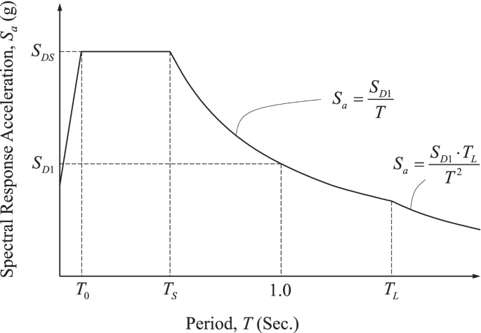
The ASCE 7 standard recognizes that seismic shear waves can be amplified as they travel through certain types of soil. The SS and S1 acceleration response parameters are, thus, modified to account for the soil characteristics at the building site. The design spectral response acceleration parameters are defined as SDS and SD1. Once these parameters have been calculated, a seismic design response spectrum is developed. The maximum magnitude of acceleration that will occur in any given structure is represented by the design response spectrum. The structure’s magnitude of acceleration in response to the ground shaking is heavily dependent on its degree of stiffness. Consequently, the acceleration magnitude in the design response spectrum varies based on the natural period of the particular structure. A typical design response spectrum is shown in Fig. 1. The final notable objective of the design criteria in ASCE 7 is to determine the Seismic Design Category for the structure based on the previously defined parameters. The Standard defines six possible seismic design categories (A through F), which are used to trigger progressively stringent requirements for the design, construction, and inspection of the structure as the magnitude of seismic hazard increases. The Standard prescriptively groups the various requirements in the SDC of Categories A through F since the requirements are often “on or off” parameters, which are not scalable (SDC stands for seismic design category).
Typical design response spectrum (reproduced based on [13])
Seismic design requirements
The ASCE 7 Standard [11] provides the required seismic analysis and design procedures specifically related to building structures. The Standard states that a mathematical model shall be constructed and evaluated for a structure to demonstrate that it is capable of resisting the internal forces and deformations that will result from the applied seismic design forces. Three types of seismic analysis procedures are presented in the Standard: i) Equivalent Lateral Force Analysis, ii) Modal Response Spectrum Analysis, and iii) Seismic Response History Procedures. With all three of these procedures, the structure is expected to behave inelastically, meaning that buckling, yielding, and permanent deformation of the structural components are expected during the design earthquake event. By allowing a certain level of damage and permanent deformation to occur in the structure, a significantly more economical building can be provided than if the structure were designed to remain entirely elastic and undamaged after the design earthquake event. A brief description of the Equivalent Lateral Force Analysis (ELF) and the Modal Response Spectrum Analysis (MRS) procedures are discussed here. A more detailed description of the Seismic Response History Procedure will be available in the next section.
The ELF method is the least rigorous of the three available methods, yet it offers sufficiently accurate results for most structures and is therefore very widely used. As previously stated, it is recognized that the seismic load is dynamic in nature and that the structure will behave inelastically under this applied seismic load. However, the ELF method utilizes two key idealizations that make the analysis much simpler: the dynamic load is converted to an equivalent static load, and the structure is assumed to behave linear elastically. The inelastic effects are accounted for through the use of a response modification factor, R, and a deflection amplification factor, Cd. The previously calculated SDS and SD1 values are modified by the R factor and the seismic importance factor, Ie, to obtain the seismic response coefficient, Cs. A Cs value represents the pseudo-acceleration of the structure and is expressed in terms of “percent gravity” units. The equations for Cs given in ASCE 7 [11] are dependent upon the structure’s fundamental period and are as follows:
where T is the fundamental period of the building and TL is the long transition period. For structures located where S1 is equal to or greater than 0.6g, Cs shall not be less than
The seismic response coefficient is then multiplied by the effective seismic weight of the structure to obtain the seismic base shear, V:
where W is the effective seismic mass of the building. The total seismic base shear, V, is vertically distributed to each of the discrete levels of the structure by use of the following equations
where Fx is the portion of the seismic base shear induced at Level x; wx is the portion of the effective seismic mass (W) that is located at or assigned to Level x; and hx is the height above the base to Level x. The vertical distribution factor Cvx uses the idealization that 100% of the structure’s mass participates in the first mode or the natural mode. All of the higher modes of the structure are neglected and the structure is reduced to one single-degree-of-freedom system, which greatly simplifies the analysis. The structure is analyzed for the series of static lateral seismic forces applied at each level, and the individual structural members are designed for the resulting forces.
The MRS approach, similar to the ELF method, uses a linear elastic idealization to simplify the analysis. The same response modification factor, R, is employed to account for the actual inelastic behavior of the structure. Whereas the ELF procedure is only interested in the first mode of vibration, MRS requires a more rigorous analysis to determine several of the natural modes of vibration of the structure. For each direction under consideration, the analysis requires that a sufficient number of modes are obtained to account for a combined modal mass participation of at least 90% of the structure’s mass. After obtaining the number of required modes, the multi-degree-of-freedom structure is converted into a series of single-degree-of-freedom systems, each of which have a unique mode shape and period of vibration. Each of the single-degree-of-freedom systems is then separately analyzed to determine the story forces, member forces, and displacements due to the design seismic loads. It should be noted that, although the MRS procedure utilizes certain dynamic properties of the structure, it is not a full-blown dynamic analysis method. The MRS results handle only the magnitude of maximum acceleration for each of the modes. Neither the sign (positive or negative), nor the time at which this maximum acceleration occurs are known. For this reason, the individual modal responses cannot be recombined exactly since their maximum values occur at a different point in time. A statistical combination of the individual modes is instead used: the outcomes from the series of uncoupled analyses are then combined through either the square root sum of squares (SRSS) or complete quadratic equation (CQC) method to attain the response of the structure.
Seismic response history procedures
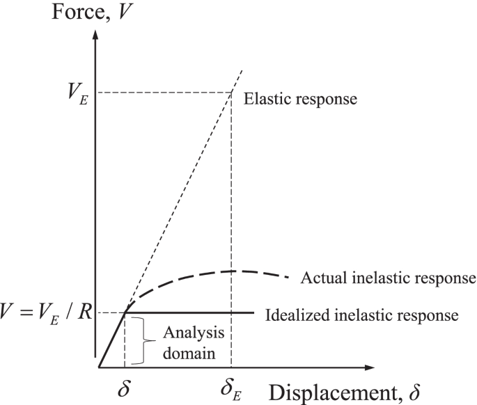
The Seismic Response History Procedures presented in ASCE 7 [11] consist of a full dynamic analysis of the structure, wherein the analytical model is subjected to a series of time-dependent ground motions. Although the use of simulated ground motions is permitted and appropriate in certain instances, the ground motions modeled in the analysis will often be from actual past seismic events recorded in the vicinity of the structure. Two subcategories exist within the Seismic Response History Procedures: the Linear Response History Procedure and the Nonlinear Response History Procedure. As is evident by their titles, the Linear Procedure utilizes the idealization that the structure will behave linear-elastically throughout the course of the dynamic seismic loading event. This is the same idealization that is made in both the ELF and the MRS procedures, and ultimately results in a much simpler and manageable analysis. This idealization can be made due to the Equal Displacement Approximation Theorem, which states that the displacement of a structure undergoing nonlinear deformation is nearly equal to the displacement of the same structure behaving linear elastically. The linear force-deformation curve can, therefore, be extrapolated out to determine an equivalent linear design force for any given deformation magnitude. Figure 2 depicts a graphical representation of the Equal Displacement Approximation Theorem concept. To the contrary, the Nonlinear Procedure assumes a nonlinear hysteretic response of the structure, which is in fact how it will behave when subjected to a real-life seismic event. The Nonlinear Procedure is obviously the more rigorous of the two analysis methods to implement; however, it should be expected to yield more accurate results because more of the actual characteristics of the structure are being captured in the mathematical model.
Equal Displacement Approximation Theorem (reproduced based on [13])
As mentioned earlier, the response history analysis is built upon a series of time-dependent ground motions as the loading parameters. Ideally, the ground motions that are selected will be analogous in nature to any future ground motions that the structure could be subjected to during an earthquake event. Therefore, the selected records should have magnitudes, fault distances, source mechanisms, and soil conditions that are all akin to what will be encountered at the project site [13]. The Pacific Earthquake Engineering Research Center (PEER) provides a large suite of past ground acceleration records that can be downloaded and implemented for a response history analysis [14]. Once a sufficient number (typically 3 to 7) of ground motions records have been selected for use in the analysis, each of the acceleration records is scaled. Scaling of the ground motions is necessary because although the type of ground motion in the record may be appropriate, it is likely that the magnitude of acceleration is either higher or lower than the acceleration that should be used for the structure being designed.
Developed from the procedures of ASCE 7 [11], the Design Response Spectrum is used as the benchmark for calculating the acceleration magnitude to which the more detailed time-dependent ground motions must be scaled. Specifically, each ground motion must be scaled so that the average of individual time-dependent spectra is not less than the demands stated in ASCE 7 [11]. The magnitude of acceleration is dependent on the natural period of the structure, so this requirement must be satisfied for the entire range of 20% to 150% of the natural period (T) of the structure under consideration. The 0.2T lower bound of the range is meant to account for the higher modes of the structure, and the 1.5T upper bound of the range is meant to account for inelastic response, which will likely have a higher period than the purely linear-elastic system. Owing to the complexity and certain subjective characteristics of the Seismic Response History Procedures, ASCE 7 [11] demands that a third-party design review be conducted on the seismic analysis and design if this procedure is implemented. The Standard states that the peer review must be documented by an independent team of registered design professionals who have demonstrated experience in the Response History Procedure. This is the only such strict requirement of a peer review found in ASCE 7 [11], which illustrates the complexity of the Seismic Response History Procedure.
Seismic retrofit of existing buildings
Modern building codes contain well defined seismic design parameters that, when properly applied, produce safe and predictable building performance during earthquakes. Seismic design provisions began making their way into building codes in the 1960s, though they were somewhat primitive and flawed in their infancy. Seismic analysis and design standards have progressively evolved over the past 40-plus years from research and industry knowledge, into what is currently in use today. Therefore, there are numerous buildings around the world that were designed and constructed prior to the enforcement of modern seismic design standards. These buildings pose a significant risk to their occupants in the event that a large earthquake should occur. Seismic retrofit is used as a means to upgrade these substandard buildings to reduce their risk of collapse and ensure the safety of their occupants.
Seismic retrofit background
The Long Beach earthquake of 1933 triggered the development of the first formal seismic building standards in the United States. Members of the California state legislature personally witnessed the collapse of buildings from the earthquake, and consequently enacted the Field Act of 1933. Through the Field Act, a statewide building code was developed with provisions to safeguard new buildings from earthquakes [15]. Although the Field Act was instrumental in providing seismic safety for newly built structures, it did not sufficiently address the considerable number of buildings constructed prior to its enactment. Recognizing this issue, the California legislature passed the Garrison Act in 1939 [15]. The Garrison Act specifically addressed California public school buildings that were built prior to 1933, requiring mandatory seismic evaluations of these structures. If the buildings were found to be substandard for seismic performance, they were required to be either retrofitted or abandoned.
Seismic design standards continued to develop at the state and local levels until the National Earthquake Hazards Reduction Program (NEHRP) was established by the U.S. Congress in 1977, with the intent “to reduce the risks of life and property from future earthquakes in the United States through the establishment and maintenance of an effective earthquake hazards reduction program.” The significance of NEHRP is that it brought the issues to the national level, providing a consistent and unified voice for earthquake risk mitigation in the United States. There are four primary Federal agencies that coordinate the activities of NEHRP and implement its programs: the Federal Emergency Management Agency (FEMA), the National Institute of Standards and Technology (NIST), the National Science Foundation (NSF), and the U.S. Geological Survey (USGS). The work of FEMA is of particular interest because the agency developed many of the fountainhead documents that lead to the current seismic design and rehabilitation provisions that are currently included in model building codes today. These include FEMA 547 (Techniques for the Seismic Rehabilitation of Existing Buildings) and FEMA P-750 (NEHRP Recommended Seismic Provisions for New Buildings and Other Structures), to name a few.
Seismic retrofit initiatives can generally be classified into two categories: mandatory programs and voluntary programs. Some local jurisdictions have implemented mandatory seismic retrofit programs for existing buildings that are deemed to be unsafe. These mandatory requirements are clearly meant to protect the safety of the public, but can come with serious political, economic, and societal side effects, and should therefore not be taken lightly. Voluntary seismic rehabilitation, carried out proactively by building owners without set requirements from the governing building jurisdiction, makes up a large percentage of retrofit projects. While motives that can drive a building owner to voluntarily retrofit their property vary widely, the most obvious one is to provide basic life safety to their occupants. Other motivations encompass protecting historic or landmark structures, minimizing disruptions and downtimes to their business, minimizing administrative efforts required to file insurance claims, and applying for disaster relief assistance. Regardless of what a particular building owner’s motive is to seismically retrofit an existing structure, there are numerous approaches for how it can be executed, which will be described in the succeeding section.
Common retrofit techniques currently in use
It is recognized that a plethora of seismic retrofit techniques are available, many of which have proven to be practical, economically viable, and effective through performance during actual earthquake events. Accordingly, a comparative review of these techniques currently in use is considered appropriate. Once a seismic deficiency is identified, there are different distinguishable classes of measures that can be taken to retrofit a building structure [16]:
-
Adding elements to increase strength or stiffness
-
Enhancing performance of existing elements by altering strength or deformation capacity
-
Improving connections between components
-
Reducing demand
-
Removing selected components from the lateral system
-
Increasing ductility
Adding new structural elements such as shear walls, braced frames, or moment frames is the most commonly used retrofit technique. The new elements are typically employed in combination with any existing lateral force resisting elements to create a new global strength and stiffness of the structure. When adding new structural elements, consideration must be given to the existing components such as diaphragms, chords, and collectors to ensure that they are capable of delivering the loads attracted by the newly introduced elements. Rather than adding new elements to the structure to improve its performance, the already existing elements of the lateral force-resisting system can be modified for upgraded performance. Examples of these methods include wrapping concrete columns with steel or composite materials to provide increased confinement and shear strength, and layering concrete and masonry shear walls with steel plates or composite materials to raise ductility and in-plane shear capacity. For this class of retrofit techniques, the vertical and horizontal distribution of seismic forces is not significantly changed because no new lateral elements are introduced to the seismic force resisting system.
Sometimes, the seismic evaluation process will reveal that the existing lateral force-resisting elements themselves have adequate strength and stiffness to resist the imposed earthquake forces, whereas the connections between these components are deficient. In these circumstances, retrofit techniques are available to improve the connections between components so that a complete load path exists and assumed force distributions can occur. This class of techniques can be classified as targeting load path deficiencies. Even if reducing the overall seismic demand is a technique that can be used when the structure contains a complete and well-connected seismic force-resisting system, it is weak relative to the design earthquake forces. One specific method within this class is lowering seismic mass, usually accomplished by removing one or more top floors, which in turn diminishes lateral load to the lower levels. This class of seismic demand reduction techniques also contains modification of dynamic response of the structure: most commonly through the use of localized damping devices or base isolation. The final class of retrofit techniques is removal of selected components from the structure. This is typically done to enhance the structure’s deformation capacity by uncoupling brittle elements from the lateral system. An example of this technique is introducing vertical sawcut joints in unreinforced masonry shear walls to change their failure mechanism from shear to a bending or rocking mode [16].
Seismic retrofit design process
The ASCE 41 document [17] is intended to be the single standard addressing the seismic performance of existing buildings. It was developed on the heels of two fountainhead guidelines: ATC-14: Evaluating the Seismic Resistance of Existing Buildings [18] and FEMA 273: NEHRP Guidelines for the Seismic Rehabilitation of Buildings [19]. Prior to these two documents, no formal standards were available for seismic evaluation and retrofit. Instead, design engineers were forced to use their individual judgment in analysis and design, usually attempting to apply standards meant for new buildings to evaluate and seismically retrofit constructed structures. Performance-based seismic design is the main approach of the provisions contained in ASCE 41 [17]. The concept of performance-based design and the specific parameters related to ASCE 41 [17] are described below.
Performance objective
The seismic design provisions of ASCE 7 [11] can generally be categorized as being prescriptive. That is, the criteria specify a minimum level of strength and stiffness of the structure, so little information is actually known about how the structure will perform during an earthquake event. For example, it is uncertain whether a building structure experiences substantial structural damage or remains fully operational with no damage. The ASCE 41 document [17], on the other hand, utilizes a performance-based approach to seismic design. This design philosophy explicitly appraises a structure’s anticipated performance for a specific seismic event it is likely to experience. Since more insight is gained regarding the building’s actual performance, the seismic force resisting system can either be made more economical while still meeting minimum performance standards, or higher levels of performance can be confirmed beyond what is assumed using the code-based prescriptive methods. Four separate sets of performance objectives are contained in ASCE 41 [17], which can be used for the seismic analysis and design of existing buildings: i) Basic Performance Objective for Existing Buildings, ii) Enhanced Performance Objectives, iii) Limited Performance Objectives, and iv) Basic Performance Objective Equivalent to New Building Standards.
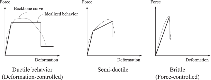
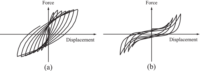
The engineer, owner, building official, or a combination of the three determine which of the four performance objectives will be utilized based on the acceptable level of seismic hazard for the particular building in question. For instance, some buildings may be required to remain fully operational after a seismic event; by contrast, other buildings may allow a substantial amount of structural damage to be acceptable, only requiring total collapse prevention, so that building occupants can safely exit the structure after a seismic event. Specific factors that are used to quantify the performance criteria listed above include the post-yield ductility of the structure, the post-yield residual strength of the structure, and the failure type of the structure. Generally, a structure is considered to be seismically superior if it can withstand large plastic deformations beyond the displacement at which it first begins to yield, and it can exhibit a post-yield ultimate strength that is substantially greater than the magnitude of the initial yield strength. Figure 3 depicts examples of various nonlinear static force-deformation curves, revealing both good and poor post-yield seismic characteristics. Likewise, the degree of hysteretic behavior displayed by the structure’s lateral force resisting system is considered when quantifying its seismic performance. Ductile hysteresis loops, as shown in Fig. 4(a), are desired since seismic loading is cyclical by nature, with the structure likely undergoing many reversible cycles of plastic deformation during an earthquake event. A pinched hysteresis loop (Fig. 4(b)) performs poorly during a seismic event on account of its inability to undergo large post-yielding deformations and dissipate the kinematic energy within the structure from the dynamically applied load. The ductility and post-elastic characteristics of various structural materials and bracing configurations are of interest in practice.
Various nonlinear force-deformation curves (reproduced based on [20])
Case studies
Delineated below are retrofit schemes illustrating the increased performance of buildings that are non-conforming to present seismic specifications. Both laboratory testing and numerical modeling are exemplified to support the effectiveness of strengthening techniques, followed by step-by-step implementations in the field.
Background
On November 15, 2017, a record-breaking earthquake with a magnitude of 5.4 occurred in the Korean peninsula. Because the region was categorized into a low/moderate seismic hazard zone [21], seismic detailing was not part of ordinary practices. As a result, serious damage took place in many buildings, particularly for those that were constructed before 2000. The natural disaster brought about more than 80 injuries and thousands of evacuees, including economic losses of 48 million US dollars [22]. Shown in Fig. 5 are representative instances displaying the archetypal damage of vertical members in a seismically deficient school building. On most occasions, the structural system of public schools was composed of reinforced concrete frames with in-filled masonry walls that raised the stiffness and strength by restraining the deformation of adjacent columns. Although the use of these moment frames was beneficial, partially filled locations owing to architectural reasons (e.g., windows) were weak spots from a load-bearing perspective. In compliance with a post-earthquake evaluation report, decisions were made to demolish one building for the safety of occupants and dozens of buildings necessitated rehabilitation. The municipal authorities were eager to identify effective solutions at affordable cost.
Retrofit methods
Among the assorted techniques discussed in a preceding section, two methods were adopted to ameliorate the seismic performance of aged school buildings: i) placing steel frames and ii) installing viscos dampers. These system-level approaches saved labor and material expenses relative to their member-level counterpart (i.e., strengthening each of the structural elements). As far as application is concerned, a few technical facets deserved attention. In other words, when mounting steel frames, integrity was of importance between the newly positioned and existing frames in order to take full advantage of the retrofit against external excitation forces. Similarly, proper interactions of the dampers with the reinforced concrete members were instrumental in alleviating hysteretic energy during an earthquake. To examine these compelling subjects, experimental investigations were necessary.
Implementation
Steel frame
Laboratory testing
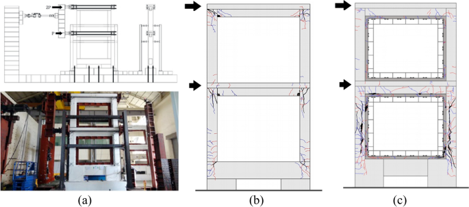
As shown in Fig. 6(a), two-story reinforced concrete frames were cyclically loaded with and without steel frames. Details about the test program are available in Lee et al. [23]. Contrary to the unstrengthened frame suffering localized cracks at beam-column joints (Fig. 6(b)), the strengthened frame revealed less cracking and distributed cracks in the upper and lower stories, respectively (Fig. 6(c)). In addition, the integrity between the steel and concrete frames was well preserved without premature failure.
Finite element modeling
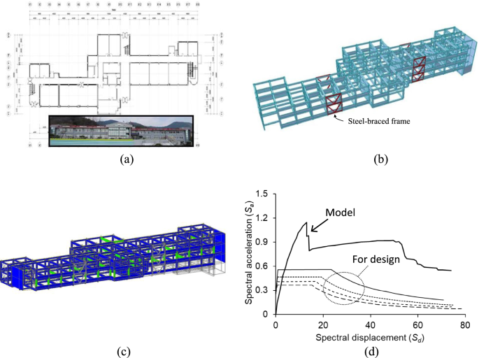
Push-over analysis was conducted to assess the efficaciousness of the frame-based retrofit method. The modeled building was part of Onjung Middle School (Fig. 7(a)), which was opened to students in 1994. The three-story structure was built with reinforced concrete frames comprising beams (300 mm by 600 mm) and columns (350 mm by 450 mm and 350 mm by 600 mm). Considering the categories specified in FEMA 356: Life Safety (LS) and Collapse Prevention (CP), equivalent to the 475-year and 975-year return periods, respectively [24], steel-braced frames were positioned at selected locations (Fig. 7(b)). After retrofitting, the maximum base shear was increased from 6,700 kN to 24,000 kN under 1.2 times the design spectral response acceleration (SDS = 0.554 and SD1 = 0.233), accompanied by distributed plastic hinges (Fig. 7(c)). The spectral acceleration associated with the developed model is graphed in Fig. 7(d).
Field application
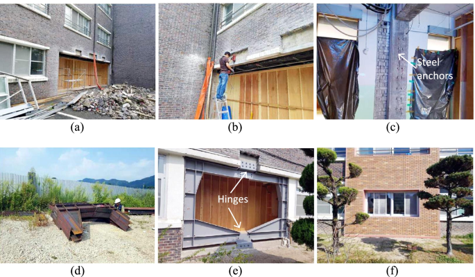
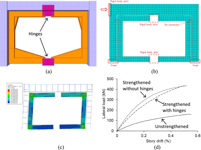
Figure 8 pictures the step-by-step procedure of the foregoing approach. The existing masonry blocks were removed (Fig. 8(a)) and in-situ material properties were measured using a non-destructive test device (Fig. 8(b)). Subsequently, steel anchors were embedded to fix prefabricated steel frames (Figs. 8(c) and (d), respectively). A set of the frames was assembled with hinges (Fig. 8(e)) and the site work was completed with restored masonry and windows (Fig. 8(f)). The purpose of situating the hinges (Fig. 9(a)) was to control dimensional tolerance while conjoining the C-shape subcomponents. The implications of these hinges were studied by finite element models (Figs. 9(b) and (c)) and, as plotted in Fig. 9(d), insignificant differences were predicted with and without the hinges.
Implementation of seismic retrofit with steel frames (photo courtesy: SeongJin Engineering Group): a removal of existing masonry wall; b in-situ measurement of material properties; c installation of steel anchors; d delivered steel frame; e installed steel frame; f restoration of windows and masonry infills
Viscos damper
Laboratory testing
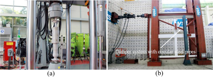
The longevity of a damper was recorded when applying a sinusoidal displacement of 10 mm at 0.5 Hz (Fig. 10(a)). Notwithstanding the marginal degradation of oscillation amplitudes during the early 3,000 cycles, resulting from a temperature change in the internal liquid, its ability to absorbing the applied energy was maintained over 10,000 cycles. Figure 10(b) exhibits a two-story reinforced concrete frame retrofitted with a three-leg damper system. The frame, containing beams (350 mm by 500 mm) and columns (350 mm by 350 mm), was not damaged up to a drift ratio of 2.0%.
Finite element modeling
The damper system was employed to upgrade the seismic resistance of the 41-year-old Donghai Elementary School building (Fig. 11(a)). Modal analysis was carried out to elucidate the dynamic characteristics and responses of the three-story framed structure (Fig. 11(b)). As informed by model predictions, five damper systems were positioned to attenuate seismic energy (Fig. 11(b)). The ramifications of the retrofit are given in Fig. 11(d): the story drift ratio was considerably reduced across Floors 1 to 3.
Field application
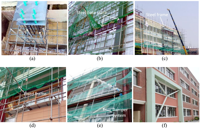
To accommodate the damper system, reinforced concrete foundations were prepared (Fig. 12(a)). After setting up steel base plates (Fig. 12(b)), a factory-made frame was erected and fixed to the building (Figs. 12(c) and (d), respectively). The three-leg damper systems were then connected to the frame (Fig. 12(e)) and painted to preclude the onset of corrosion (Fig. 12(f)).
Implementation of seismic retrofit with viscous dampers (photo courtesy: San Engineering & Construction Architects and Techsquare Co.): a reinforcement of concrete foundation; b placement of steel plates; c lifting of steel frame; d installation of steel frame; e installation of damper; f completion
Concluding remarks
This paper has dealt with a comprehensive overview of seismic analysis, design, and retrofit for built-environments. The noticeable advances that have been made since the 1960s enabled the reliable operation and management of modern buildings under earthquake-induced distress. Complying with regulatory provisions stipulated in specifications and guidelines, practitioners furnish professional services to fulfill procedural requirements in a given situation, which are contingent upon predefined functionality, importance, and constraints. Oftentimes, approximate and conservative methods are preferred to simplify complex problems and to handle potential uncertainties in the field. Special attention should be paid to structures that were designed pursuant to outdated codes, especially for those possessing seismic deficiencies and thereby directly exposed to critical risks when subjected to unexpected ground motions. Unlike the case of newly constructed buildings, there may be unavoidable restraints in updating aged ones; as a consequence, project-specific settings are commonplace. Performance-based retrofit is a favorable alternative to conventional prescriptive approaches in the context of reflecting unique attributes, saving a construction and maintenance budget, and attempting tailored strategies. Rehabilitated members benefit from increased stiffness, strength, and deformability as well as from reduced external forces and accelerations by installing energy-absorbing systems. Regarding the selection of retrofit schemes, response spectra and hazard levels should be taken into account alongside anticipated failure modes. The case studies presented herein imparted simple yet adoptable technologies that can intensify seismic resistance of non-conforming buildings in a systematic manner, corroborated by laboratory testing and finite element modeling. Continued endeavors are indispensable to push forward the state of the art for the sake of achieving a sustainable society.
Availability of data and materials
The datasets used and/or analyzed during the current study are available from the corresponding author on reasonable request.
References
Kappos A, Penelis GG (2014) Earthquake resistant concrete structures. CRC Press, Boca Raton
EPRI (2012) Seismic evaluation guidance: screening, prioritization and implementation details (SPID) for the resolution of Fukushima near-term task force recommendation 2.1: seismic, Electric Power Research Institute, Report No. 1025287, Palo Alto: Electric Power Research Institute.
Pohoryles, D.A. and Bournas, D.A. 2020. Seismic retrofit of infilled RC frames with textile reinforced mortars: State-of-the-art review and analytical modelling, Composites Part B, 183, 107702.
Fung JF, Sattar S, Butry DT, McCabe SL (2021) The total costs of seismic retrofits: state of the art, Earthquake Spectra, in-press. https://doi.org/10.1177/87552930211009522
Nigam, P.K. and Akhtar, S. 2021. Retrofitting practices in various categories of RCC structures: a comprehensive review, Materialstoday: Proceedings, 45(7), 7123-7131.
Attard TL, Abela CM, Dhiradhamvit K (2011) Seismic FRP retrofit of circular single-column bents using a ductility wrap envelope to alter failure modes. Eng Struct 33:1553–1564
Lignos DG, Moreno DM, Billington SL (2014) Seismic retrofit of steel moment-resisting frames with high-performance fiber-reinforced concrete infill panels: large-scale hybrid simulation experiments. J Struct Eng 140(3):04013072
Zafar A, Andrawes B (2015) Seismic behavior of SMA-FRP reinforced concrete frames under sequential seismic hazard. Eng Struct 98:163–173
Caterino N, Nuzzo I, Ianniello A, Varchetta G, Cosenza E (2021) A BIM-based decision-making framework for optimal seismic retrofit of existing buildings. Eng Struct 242:112544
Gara F, Carbonari S, Roia D, Balducci A, Dezi L (2021) Seismic retrofit assessment of a school building through operational modal analysis and f.e. modeling. J Structural Eng 147(1):040220302
ASCE (2022) Minimum design loads and associated criteria for buildings and other structures (ASCE/SEI 7-22). American Society of Civil Engineers, Reston
USGS (2022) Maps of earthquake shaking hazards. U.S. Geological Survey, Reston
FEMA (2009) Engineering guideline for incremental seismic rehabilitation (FEMA 420). Federal Emergency Management Agency, Washington, D.C.
PEER (2022) String ground motion databases. Pacific Earthquake Engineering Research Center, University of California, Berkeley
DGS (2002) Seismic safety inventory of California public schools, a report to the Governor of California and the California State Legislature. Department of General Services, Sacramento
FEMA (2006) Techniques for the Seismic Rehabilitation of Existing Buildings (FEMA 547). Federal Emergency Management Agency, Washington, D.C.
ASCE (2017) Seismic evaluation and retrofit of existing buildings (ASCE/SEI 41-17). American Society of Civil Engineers, Reston
ATC (1987) Evaluating the seismic resistance of existing buildings. Applied Technology Council, Redwood City
FEMA (1997) NEHRP Guidelines for the seismic rehabilitation of buildings (FEMA 273). Federal Emergency Management Agency, Washington, D.C.
FEMA (2005) Improvement of nonlinear static seismic analysis procedures (FEMA 440). Federal Emergency Management Agency, Washington, D.C.
Han S-W, Choi Y-S (2008) Seismic hazard analysis in low and moderate seismic region-Korean peninsula. Structural Safety 30(6):543–558
KMIS (2017) Pohang earthquake white paper: from the occurrence of the Pohang earthquake to the recovery, and the remaining tasks, Report No. 2018. 11-1741000-000123-01. Korean Ministry of Interior and Safety, Sejong
Lee H-J, Lee H-B, Park H-G, Lee J-K (2021) Cyclic loading test for two-story RC moment frames retrofitted with internal steel frames. J Structural Eng 147(2):04020333
FEMA (2000) Prestandard and Commentary for the Seismic Rehabilitation of Buildings (FEMA 356). Federal Emergency Management Agency, Washington, D.C.
Acknowledgements
The authors gratefully acknowledge various industry partners that participated in the case studies.
Funding
Not applicable.
Author information
Authors and Affiliations
Contributions
JHK and CJH drafted the manuscript; YJK conceived the scope and contents of the research and wrote the manuscript; and HGP supervised the project, supplied technical data, and reviewed the manuscript. The author(s) read and approved the final manuscript.
Corresponding author
Ethics declarations
Ethics approval and consent to participate
Not applicable.
Consent for publication
Not applicable.
Competing interests
The authors declare that they have no competing interests.
Additional information
Publisher’s Note
Springer Nature remains neutral with regard to jurisdictional claims in published maps and institutional affiliations.
Rights and permissions
Open Access This article is licensed under a Creative Commons Attribution 4.0 International License, which permits use, sharing, adaptation, distribution and reproduction in any medium or format, as long as you give appropriate credit to the original author(s) and the source, provide a link to the Creative Commons licence, and indicate if changes were made. The images or other third party material in this article are included in the article's Creative Commons licence, unless indicated otherwise in a credit line to the material. If material is not included in the article's Creative Commons licence and your intended use is not permitted by statutory regulation or exceeds the permitted use, you will need to obtain permission directly from the copyright holder. To view a copy of this licence, visit http://creativecommons.org/licenses/by/4.0/.
About this article
Cite this article
Kim, JH., Hessek, C.J., Kim, Y.J. et al. Seismic analysis, design, and retrofit of built-environments: a procedural review of current practices and case studies. J Infrastruct Preserv Resil 3, 11 (2022). https://doi.org/10.1186/s43065-022-00056-3
Received:
Accepted:
Published:
DOI: https://doi.org/10.1186/s43065-022-00056-3
